
This large industrial plant, which was part of a large global shipping company, located in the Eastern United States received thousands of parcel packages a day. After the packages came in, they were for reloading into large box trucks for delivery out into the regions surrounding the plant. The sorting process involved passing the packages through many conveyor systems before they reached the proper trucks.
The plant had been part of the shipping company’s system for almost 40 years. It was originally designed as parcel package processing center. All of the sorting & routing equipment inside the plant used some vintage & form of variable frequency drives (VFDs) in conjunction with programmable logic controllers (PLCs) & industrial power supplies (IPSs). The size of the VFDs ranged from a few horsepower to almost 100 horsepower. The vintage of the VFDs ranged from the 1990s to 2018. The plant used approximately 200 VFDs spread all over the plant.
The plant was powered by two feeders from the utility’s substation with a feeder voltage of 12.47 kV. These feeders delivered power to two ordinary stepdown transformers which stepped the voltage down to 4.16 kV at the secondaries. One side of the 4.16-kV bus was used to power three larger chillers powered by soft start systems. The other side of the 4.16-kV bus delivered power to four rooftop dual-ended switchgear systems. Each system had its own stepdown transformer which stepped the voltage down from 4.16 kV to 480 volts which powered the equipment out in the plant. The plant’s electrical system was original & had not been updated since it was installed. At the time it was designed & installed, virtually no electronic loads were being used by end users, so its design didn’t incorporate any best power quality engineering practices.
One day, the plant began to experience IPS failures. IPSs were used in most of the power / control cabinets where VFDs & PLCs were also used to power & control the conveyor systems. After about 30 IPSs had failed over a period of six months, the plant manager reached out to the company’s engineering department for assistance. Collaboration between the plant manager & the Director of Engineering resulted in them finding & contacting PBE Engineers to discuss their IPS failures & what to do next.
After a discussion between the plant manager, Director of Engineering & an engineer from PBE, the company requested that PBE assemble a plan in the form of a proposal to visit the plant & gather additional information & install some power quality monitoring equipment that could be controlled remotely. The PBE engineer who visited the plant walked through the plant, examined the power / control cabinets where IPSs had failed & further discussed the problems with the plant manager, the plant’s staff electrician, the maintenance manager & several line operators who knew how the equipment had been behaving. Other important information was gathered which aided PBE in conducting the evaluation to determine why the IPSs had been failing.
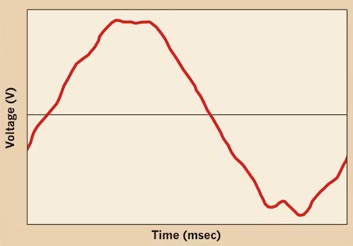
The PBE engineer installed the monitoring equipment at the main & at the mains of the switchgear stations on the rooftops. Upon installing the monitoring equipment, the PBE engineer noticed that the line voltage was very distorted at the 12.47-kV main, at the 4.16-kV mains & at the 480-V secondaries. The distortion was so severe that the RMS voltage on the 480-V buses was much lower than expected.
A few days after PBE installed the monitoring equipment, PBE received a phone call from the plant manager. About the time the phone call came in, PBE received a notification from one of the monitors that an outage had occurred on some of the 480-V buses that run the plant. The plant manager told PBE that about one-half of the plant had gone down.
The plant manager contacted the plant electrician to start determining what had happened on the plant’s electrical system to cause the outage while PBE was travelling to the plant to investigate the failure & gather additional information.
While PBE was in route to the plant, the plant’s electrician determined that one of the main internal transformers that stepped the 12.47-kV main bus down to 4.16-kV had failed. These transformers were part of the main switchgear system on the main floor of the building. Upon finding the transformer failure, the plant’s electrician found that the transformer was very hot. He operated the tie breaker on the main system to shift the load over to the other side of the 12.47-kV bus, so the plant manager could work with his crew & restart the plant.
The PBE engineer collected some additional information about the transformer failure while there. The plant’s electrician started making arrangements to get the failed transformer removed, so a new one could be installed soon. While PBE was at the plant, some other discussions were held with the plant & maintenance managers.
While still at the plant, the PBE engineer contacted PBE’s PQ monitoring engineer to discuss the data that had been collected over the past few days before the transformer failure. PBE discovered that some of the harmonic currents were elevated above acceptable limits defined in IEEE 519. (IEEE 519 is a harmonic control standard written mainly for utility companies to help ensure they maintain control over harmonic voltages at the Points of Common Coupling (PCCs) between the utility & the customer. IEEE 519 can be used to help guide customers on managing harmonic voltages & currents.)
Concerned about the other transformers in the plant, the PBE engineer discussed with the plant & maintenance managers about taking & monitoring the temperature of the other transformers. The customer agreed to pay the additional cost allowing PBE to install the sensors & gather important data regarding the static & dynamic temperature performance of the transformers. The PBE engineer installed the additional equipment to gather the thermal data from each transformer, so PBE could track the temperature of the transformers as the plant continued to operate. (The plant load fluctuates each week based on the number of packages processed between & during specific seasons.) This information was important, since it would allow PBE to determine the thermal profile of the transformers including their maximum value as well as the electrical conditions change that resulted in the transformer reaching its maximum temperature.
While the monitors were collecting additional voltage, current & transformer data, PBE engineers were busy preparing for a harmonic analysis of the plant’s electrical system. PBE knew from the visits that the plant was using a diverse selection of VFDs with varying harmonic performance. It was apparent that much of the plant was using VFDs that required significant harmonic currents. From a comparison, PBE determined that VFDs using 6-pulse to 18-pulse switching were being used in the plant. PBE also determined that not enough harmonic cancellation was occurring, hence the high harmonic currents at the main & switchgear transformers.
From a detailed harmonic analysis of the plant’s electrical systems & its electronic loads, PBE determined that an excessive level of 7th, 9th & 13th harmonic currents were present in the system. These currents were significant contributors to the distorted voltage as well as the high transformer temperatures. Moreover, these currents were adding extra heat to the switchgear bus bars & the power cables. PBE informed the technical staff that allowing the flow of these harmonics degrades the insulation on the power cables. PBE determined that custom harmonic filtering was required at the 480-volt secondary side of the transformers.
PBE was now busy at work with several harmonic filter manufacturers to come up with the best harmonic filter design & installation to lower the high harmonics to values safe for the plant’s electrical system. PBE also determined that the IPSs were sensitive to some of the voltage harmonics that were applied to the power supply’s inputs. This is what caused the power supplies to experience a shorter than normal life.
From this case study, one can see that keeping up with the harmonic performance of an industrial plant is critical to the life & performance of the plant’s electrical system and to the life & performance of the plant’s electronic equipment. Installing the right type of advanced power quality monitoring equipment at the right locations on the plant’s electrical system would have documented the data necessary to track the level of harmonic currents, harmonic voltage distortion & total harmonic power being lost to the harmonics. Such monitoring is critical in maintaining the electrical & financial performance of the plant from the point where electronic loads started to be installed to its present point in time. Analysis of such harmonic data would have allowed the consideration of other harmonic mitigation methods to control the harmonic currents that have already shortened the life of its electrical system & equipment.
Want to learn more about PQ & keep up with new PQ problems facing customer facilities, plus much more? Subscribe to one of PBE Engineers’ newsletters that’s free!